
VHF-UHF Long Boom, High Performance Antenna Designs by W8IO
(links updated 12 Aug 2017)
This page documents the various long boom VHF-UHF antenna designs that I have created. Some are entirely new designs and others are optimized versions of popular Ham designs. The entirely new antenna designs are called Loggi's. More information on the Loggi design can be found here. The optimized designs are typically popular VHF long Yagi designs that I have peaked for F/R greater than 30 dB in both the E and H planes. If possible to achieve in the same design, I will also try to improve the first sidelobe levels in both planes. Usually, these optimizations are associated with a slight decrease in forward gain (less than 0.1 dB).
| Model | Directive Gain (dBi) | G/T | E-F/R (dB) | H-F/R (dB) | Boom Length (feet) | Boom Length (m) | NEC file | EZNEC file | Az Pattern | Elev Pattern |
| Loggi-144-27A1 | 16.05 | -1.47 | 38.27 | 32.68 | 25.85 | 7.88 | 144-27A1 | - | - | - |
| Loggi-144-27A5 | 16.19 | -1.29 | 34.98 | 34.03 | 25.85 | 7.88 | 144-27A5 | - | - | - |
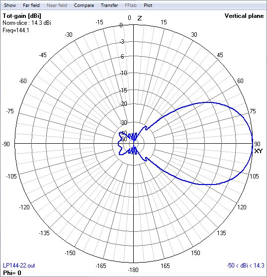
| W8IO-LP144-22 | 14.3 | - | 35 | 35 | 22 | - | LP144-22 | LP144-22 | LP144-22-az | LP144-22-el |
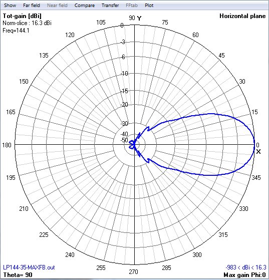
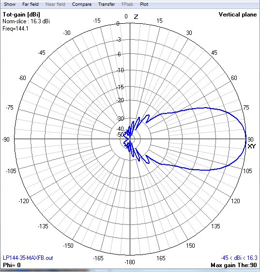
| W8IO-LP144-35-MAXFB | 16.34 | - | 48 | 37 | 32 | 9.7 | LP144-35MAXFB | LP144-35MAXFB | LP144-35-MFB-az | LP144-35-MFB-el |
| - |
- |
- | - |
- | - |
- | - | - | ||
| - | - | - | - | - | - | - | - | - | - |
W8IO 50 MHz long boom Yagi and LPDA data (16-45 foot booms)
| Model | Directive Gain (dBi) | +/- Gain (DL6WU equation) | E-F/R (dB) | H-F/R (dB) | E-SLL (dB) | H-SLL (dB) | Boom Length (feet) | Boom Length (m) | Boom Length (lambda) | NEC file | EZNEC file | Az Pattern | Elev Pattern |
| Loggi-50-7 | 11.09 | +0.42 | 25.7 | 20.35 | none | -20.1 | 16 | 4.81 | 0.8 | Loggi-50-7 | - | - | - |
| Loggi-50-8 | 11.69 | +0.54 | 23.27 | 23.27 | -30 | -16.6 | 18 | 5.53 | 0.92 | Loggi-50-8 | - | - | - |
| LP50-9FB | 11.77 | -0.46 | 34.38 | 28.23 | none | -24.6 | 24.8 | 7.57 | 1.27 | - | - | - | - |
| Loggi-50-9 | 12.25 | +.01 | 31 | 22.7 | -31.5 | -19.9 | 24.9 | 7.6 | 1.28 | Loggi-50-9 | - | - | - |
The antennas shown in red are experimental and have not yet been built or tested. F/R includes all backlobes.
The DL6WU gain curve can be written as GAIN (dBi) = 7.773 * LOG (Length / Lambda) + 11.43
W8IO 144
MHz long boom Yagi data (20-42 foot booms)
| Model | Directive Gain (dBi) |
4 bay G/T (dB) |
+/- Gain (DL6WU equation) |
YagiCAD G/T (dB) |
E-F/R (dB) | H-F/R (dB) | E-SLL (dB) |
H-SLL (dB) |
Boom Length (feet) | Boom Length (m) | Boom Length (lambda) |
NEC file | EZNEC file | Az Pattern | Elev Pattern |
| W8IO-144-12V | 15.63 | - | +0.20 | - | 33.15 | 27.54 | - | -17.0 | 22.3 | 6.8 | 3.27 | 144-12V | - | - | - |
| W8IO-144-13V | 16.01 | - | +0.18 | - | 34.68 | 28.85 | -21 | -17.3 | 25.1 | 7.65 | 3.68 | 144-13V | - | - | - |
| W8IO-144-14V* | 16.27 | -1.18* | +0.18 | - | 34.06 | 30.04 | -21.2 | -17.7 | 27.16 | 8.28 | 4.0 | 144-14V | 144-14V | 144-14V-az | 144-14V-el |
| W8IO-144-14V2 | 16.27 | - | +0.18 | - | 35 | 31 | -21.1 | -17.6 | 27.16 | 8.28 | 4.0 | - | - | - | - |
| W8IO-144-15V | 16.58 | -0.80** | +0.15 | - | 34.33 | 31.53 | -20.7 | -17.5 | 30.0 | 9.14 | 4.4 | 144-15V | 144-15V | 144-15V-az | 144-15V-el |
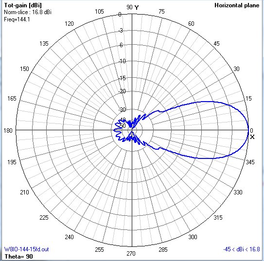
| W8IO-144-15FD | 16.81 | -0.57** | +0.14 | - | 32.33 | 27.11 | -23.2 | -20.5 | 32.3 | 9.85 | 4.73 | 144-15FD | 144-15FD | 144-15FD-az | 144-15FD-el |
| W8IO-144-16V | 16.87 | -0.55** | +0.20 | - | 35.8 | 32.3 | -19.6 | -16.8 | 32.3 | 9.86 | 4.73 | 144-16V | 144-16V | 144-16V-az | 144-16V-el |
| W8IO-UR5EAZ-16V* | 16.94 | -0.45*** | +0.27 | - | 36.15 | 32.18 | -19.2 | -16.4 | 32.3 | 9.85 | 4.73 | W8IO-UR5EAZ-16V | 144-16V | - | - |
| W8IO-144-17V | 17.11 | -0.27*** | +0.18 | - | 35.48 | 32.34 | -19.2 | -16.5 | 34.8 | 10.6 | 5.1 | 144-17V | 144-17V | 144-17V-az | 144-17V-el |
| W8IO-144-18V | 17.29 | -0.09*** | - | - | 35.54 | 32.69 | -18.7 | -16.2 | 37 | 11.3 | 5.43 | 144-18V | 144-18V | 144-18V-az | 144-18V-el |
| W8IO-144-18V2 | 17.42 | -0.07*** | +0.28 | - | 34.08 | 30.07 | -17.9 | -15.5 | 37 | 11.3 | 5.43 | 144-18V2 | 144-18V2 | 144-18V2-az | 144-18V2-el |
| W8IO-144-19V | 17.62 | +0.17*** | +0.234 | - | 34.81 | 32.37 | -17.9 | -15.6 | 39.9 | 12.15 | 5.84 | 144-19V | 144-19V | 144-19V-az | 144-19V-el |
| W8IO-144-20V | 17.87 | +0.36*** | +0.28 | - | 37.04 | 31.63 | -17.7 | -15.6 | 42 | 12.9 | 6.2 | 144-20V | 144-20V | 144-20V-az | 144-20V-el |
The antennas shown in red are experimental and have not yet been built or tested. These are all optimized versions of popular Ham designs. The antennas shown with * have complete instructions for building. Models ending in "V" have a "V" shaped driven element. Models ending in "U" have a "U" shaped reflector. Models ending in "FD" have a horizontal folded dipole as the driven element. F/R includes all backlobes. For the YagiCAD G/T, Tsky=200 and Tearth = 1000.
# These G/T values are calculated based on stacking distances of 4.2m (E-plane) and 4.0m (H-plane).
* These G/T values are calculated based on stacking distances of 4.4m (E-plane) and 4.2m (H-plane).
** These G/T values are calculated based on stacking distances of 4.6m (E-plane) and 4.4m (H-plane).
*** These G/T values are calculated based on stacking distances of 4.8m (E-plane) and 4.6m (H-plane).
The DL6WU gain curve can be written as GAIN (dBi) = 7.773 * LOG (Length / Lambda) + 11.43
Another good gain curve for yagis is given by Tom Ring, WA2PHW/K0TAR: Gain (dBd) = 10 * LOG (5.4075 * (Length/Lambda) + 4.25)
W8IO 222 MHz long boom Yagi data (19-35 foot booms)
| Model | Directive Gain (dBi) |
4 bay
G/T (dB)
|
+/- Gain (DL6WU equation) |
YagiCAD G/T (dB) |
E-F/R (dB) | H-F/R (dB) | E-SLL (dB) |
H-SLL (dB) |
Boom Length (feet) |
Boom Length (m) |
Boom Length (Lambda) |
NEC file | EZNEC file | YagiCAD file | Az Pattern | Elev Pattern |
| W8IO-222-15V | 16.61 | +3.23** | +0.18 | - | 34.39 | 31.3 | -20.6 | -17.6 | 19.5 | 5.9 | 4.4 | W8IO-222-15V | W8IO-222-15V | W8IO-222-15V | W8IO-222-15V-az | W8IO-222-15V-el |
| W8IO-222-16V | 16.9 | +3.53** | +0.22 | - | 35.71 | 31.48 | -19.6 | -16.9 | 21 | 6.4 | 4.74 | W8IO-222-16V | W8IO-222-16V | W8IO-222-16V | W8IO-222-16V-az | W8IO-222-16V-el |
| W8IO-222-17V | 17.15 | +3.84** | +0.22 | - | 34.77 | 31.76 | -19.1 | -16.9 | 22.56 | 6.88 | 5.1 | W8IO-222-17V | W8IO-222-17V | W8IO-222-17V | W8IO-222-17V-az | W8IO-222-17V-el |
| W8IO-222-18V | 17.33 | +4.13*** | +0.19 | - | 35.54 | 32.69 | -18.6 | -16.3 | 24 | 7.33 | 5.43 | W8IO-222-18V | W8IO-222-18V | W8IO-222-18V | W8IO-222-18V-az | W8IO-222-18V-el |
| W8IO-222-19V | 17.58 | +4.41*** | +0.20 | - | 37.76 | 36.28 | -18.0 | -15.8 | 25.87 | 7.887 | 5.84 | W8IO-222-19V | W8IO-222-19V | W8IO-222-19V | W8IO-222-19V-az | W8IO-222-19V-el |
| W8IO-222-20V | 17.90 | - | +0.31 | - | 35.55 | 31.09 | -17.6 | -15.7 | 27.46 | 8.37 | 6.2 | W8IO-222-20V | W8IO-222-20V | W8IO-222-20V | W8IO-222-20Vaz | W8IO-222-20Vel |
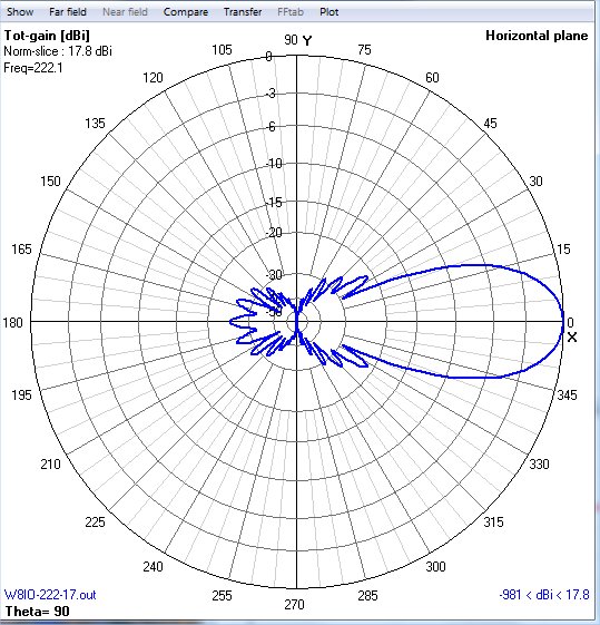
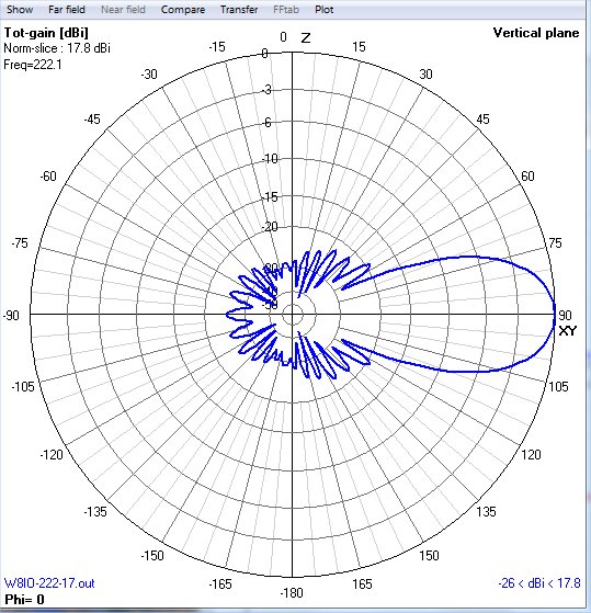
| W8IO-222-17 | 17.94 | - | +0.53 | -1.82 | 24.8 | 24.8 | -21.3 | -19.5 | 26 | 7.932 | 5.875 | W8IO-222-17 | W8IO-222-17 | W8IO-222-17 | W8IO-222-17az | W8IO-222-17el |
| W8IO-222-18 | 18.14 | +4.60### | +0.53 | -1.71 | 30.9 | 28.7 | -20.1 | -18.4 | 27.6 | 8.43 | 6.24 | W8IO-222-18 | W8IO-222-18 | W8IO-222-18 | W8IO-222-18-az | W8IO-222-18-el |
| W8IO-222-19 | 18.12 | +4.82### |
+0.24 | -1.37 | 29.05 | 28.42 | -21.4 | -19.7 | 30 | 9.1 | 6.76 | W8IO-222-19 | W8IO-222-19 | W8IO-222-19 | W8IO-222-19az | W8IO-222-19el |
The antennas shown in red are experimental and have not yet been built or tested. F/R includes all backlobes. For the G/T, Tsky=70 and Tearth = 600.
** These G/T values are calculated based on stacking distances of 3.4m (E-plane) and 3.3m (H-plane).
*** These G/T values are calculated based on stacking distances of 3.5m (E-plane) and 3.4m (H-plane).
### These G/T values are calculated based on stacking distances of 3.6m (E-plane) and 3.5m (H-plane).
The DL6WU gain curve can be written as GAIN (dBi) = 7.773 * LOG (Length / Lambda) + 11.43
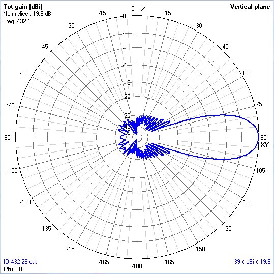
W8IO 432 MHz long boom Yagi data
(14-32 foot booms)
| Model | Directive Gain (dBi) |
4 bay
G/T (dB)
|
Stacking Distance for G/T | +/- Gain (DL6WU equation) |
YagiCAD G/T (dB) |
E-F/R (dB) | H-F/R (dB) | E-SLL (dB) |
H-SLL (dB) |
E-BW (deg) | H-BW (deg) | Boom Length (feet) | Boom Length (m) | Boom Length (Lambda) |
NEC file | EZNEC file | YagiCAD File |
Az Pattern | Elev Pattern |
| W8IO-432-20V | 17.98 | 9.18 | 1.85m | +0.28 | - | 33.4 | 30.4 | -16.5 | -14.6 | 14.1 | 4.3 | 6.2 | W8IO-432-20V | W8IO-432-20V | - | W8IO-432-20V | W8IO-432-20V | ||
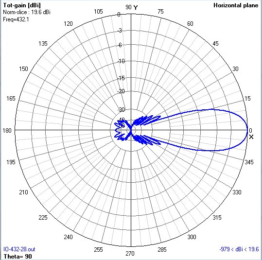
| W8IO-432-28 | 19.69 | - | 2m | +0.23 | 4.89 | 32.7 | 30.8 | -23 | -22 | 24.6 | 7.5 | 10.8 | W8IO-432-28 | W8IO-432-28 | W8IO-432-28 | W8IO-432-28az | W8IO-432-28el | ||
| W8IO-432-29 | 19.79 | 10.79 | 2.3m | +0.204 | 5.0 | 33.55 | 31.55 | -23.6 | -22.5 | 25.6 | 7.8 | 11.2 | W8IO-432-29 | W8IO-432-29 | W8IO-432-29 | W8IO-432-29 | W8IO-432-29 | ||
| Hy-Gain 7031DX | 19.74 | 10.29 | 2.4m | +0.398 | 4.35 | 27.6 | 27.0 | -19.5 | -18.4 | 23.72 | 7.23 | 10.42 | 7031DX | 7031DX | 7031DX | 7031DX-az | 7031DX-el | ||
| W8IO-432-31* | 19.84 | 10.61 | 2.5m | +0.498 | 4.66 | 28.46 | 27.78 | -19.3 | -18.4 | 20.5 | 21 | 23.72 | 7.23 | 10.42 | W8IO-432-31 | W8IO-432-31 | W8IO-432-31 | W8IO-432-31az | W8IO-432-31el |
| W8IO-432-32* | 20.03 | 10.49 | 2.3m | +0.552 | 30.84 | 27.99 | -18.3 | -17.3 | 20 | 20 | 24.69 | 7.525 | 10.85 | W8IO-432-32 | |||||
| W8IO-432-33* | 20.10 | 10.95 | 2.3m | +0.519 | 5.12 | 28.01 | 27.96 | -18.8 | -17.9 | 20 | 20.5 | 25.54 | 7.78 | 11.22 | W8IO-432-33 | W8IO-432-33 | W8IO-432-33 | W8IO-432-33 | W8IO-432-33 |
| W8IO-432-35* | 20.37 | 11.15 | 2.4m | +0.543 | 5.33 | 31.31 | 28.32 | -18.6 | -17.6 | 19.2 | 19.6 | 27.37 | 8.34 | 12.03 | W8IO-432-35 | ||||
| W8IO-432-37* | 20.64 | 11.42 | 2.4m | +0.596 | 5.6 | 30.55 | 28.95 | -18.2 | -17.2 | 18.8 | 19.2 | 29.2 | 8.9 | 12.83 | W8IO-432-37 | ||||
| W8IO-432-40* | 21.04 | 11.78 | 2.4m | +0.692 | 5.96 | 33.0 | 29.09 | -17.2 | -16.4 | 17.8 | 18.0 | 32.0 | 9.74 | 14.04 | W8IO-432-40 |
VHF-UHF
Misc Antenna Links
Element Length Correction due to Boom
The VHF/UHF antenna NEC files shown above include the "raw" element lengths. That is, the element lengths are those used with a wood or plastic (dielectric) boom or supported above or below a metal boom with an large insulator. To convert these raw lengths into actual lengths used when passed through the center of metal booms, you need to add a correction factor, based on whether the element is insulated and passes through the center of a metal boom, or is shorted directly to the metal boom with a clamp. If the element is insulated when it passes through the metal boom, the correction factor is approximately 15% the diameter of the boom. For example, for a 36" (raw length) insulated element passed through the center of a 1" metal boom, the YU7EF correction factor is 0.15", so the actual length should be 36.15" when built. The table below gives correction factors for common US boom diameters.
| Boom Diameter (inches) | DL6WU/G3SEK
insulated element THRU metal boom correction factor (inches) |
YU7EF insulated
element THRU metal boom correction factor (inches) |
YU7EF insulated
element ABOVE metal
boom correction
factor (inches)
|
| 0.875 | 0.106 | 0.125 | 0.031 |
| 1.000 | 0.137 | 0.150 | 0.0375 |
| 1.125 | 0.170 | 0.188 | 0.047 |
| 1.250 | 0.206 | 0.215 | 0.0538 |
| 1.375 | 0.246 | 0.255 | 0.0638 |
| 1.500 | 0.289 | 0.295 | 0.0738 |
| 1.625 | 0.333 | 0.340 | 0.085 |
| 1.750 | 0.380 | 0.385 | 0.096 |
Various antenna experimentors have similar correction factors, as shown below.
Here is a link to YU7EF's Boom Correction Notes.
Here is a link to YU1AW's Boom Correction article.
Here is information from the VHF/UHF Long Yagi Workshop.
Here is a link to DG7YBN's Boom Correction Notes and his Practical Yagi Building page.
Here is a link to SM5BSZ's collection of Boom Correction information.
The plastic element insulators and stainless steel keepers may be purchased from Directive Systems here in the US.Here are some ideas and hints to help with your home antenna construction.
Comments and corrections/additions are welcome!
contact Roger: email to
rgcox2 (at) gmail.com
Roger Cox W8IO - Spring Lake, MI